Welcome back to another installment of our Make It Monday series. Today we are going to outline an amp mod that we get asked about fairly often, which is a master volume mod for our British 45 Style Amp Kit. This is a simple mod that won’t take much time, but will definitely allow you to get a wonderfully gainy sound out of your amp without having to crank the volume up too high.
To make it easy, we’ve created a British 45 Master Volume Mod Kit which consists of all the parts you’ll need to complete this modification. And honestly, there are only three actual parts you’ll need: (1) 1M Potentiometer, (1) British Style Knob, and (3) Feet of wire. On a slightly more technical level, what we are doing is placing an additional volume control between the preamp and power amp by replacing the speaker extension jack with the mod kit itself.
Here’s a quick list of things you’ll need to get the job done:
British 45 Master Volume Mod KitSoldering IronSolderWire StrippersNeedle Nose PliersNut DriverSmall Flathead Screwdriver
Before we get started, we’ll need to remove our chassis from its cabinet and get it onto our work bench. Next, as always, let’s drain our filter caps for the sake of safety. If you are unfamiliar with this procedure, please check out our article outlining Filter Cap Drainage Procedures before proceeding.
Okay now that we’re super safe, let’s dive in. First, we will need to remove the wire that runs from the middle lug on the treble control pot to the input capacitor on the phase inverter. These points are outlined in Images 1A and 2A below…
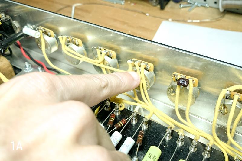
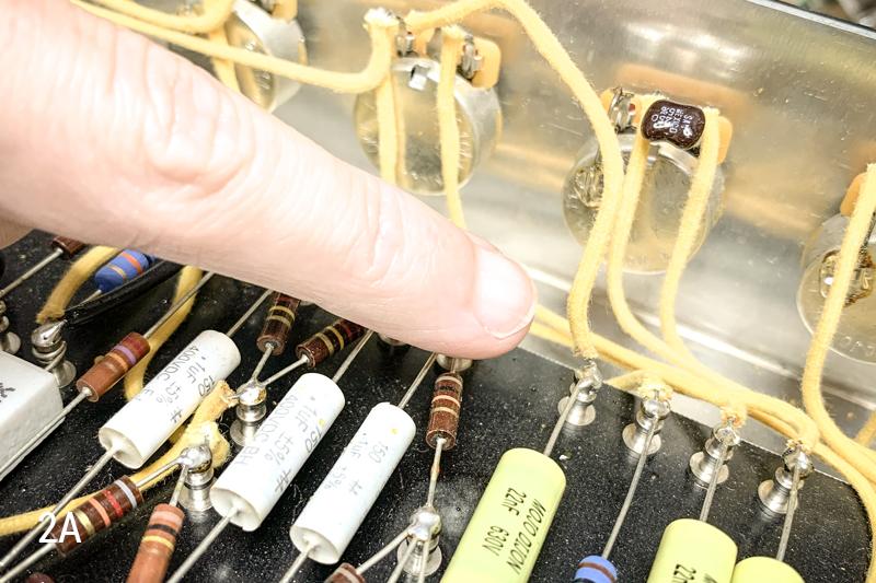
Grab your needle nose pliers and your soldering iron, heat up the contact on the potentiometer, and pull the wire away. Then repeat this on the other end of the wire.
Next, it’s time to remove the two wires that run between your speaker jacks on the backside of the chassis. Take a look at Images 3A and 4A below for a visual…
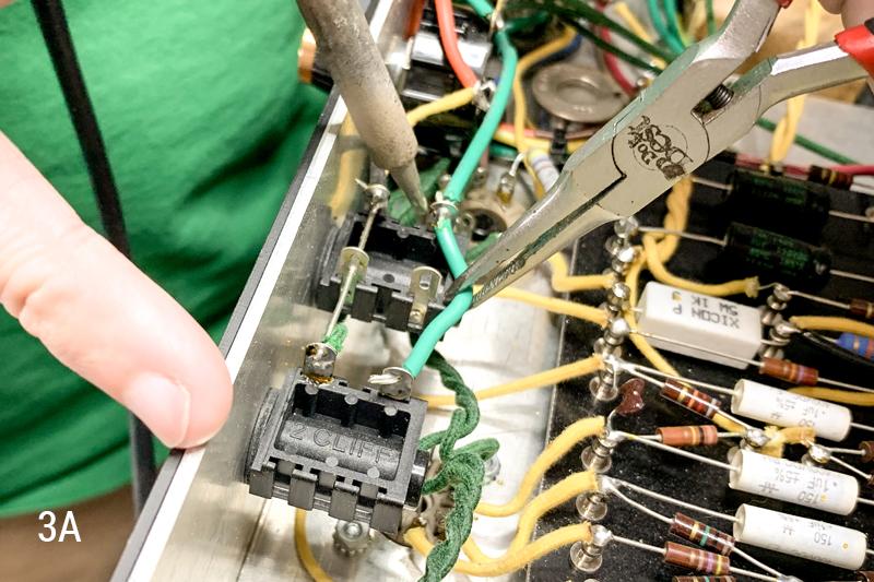
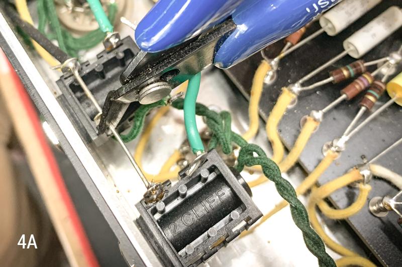
To remove these wires you can heat the contact points and pull them out with your pliers, as we did earlier. In some cases you may be able to use wire cutters to simply trim these wires out.
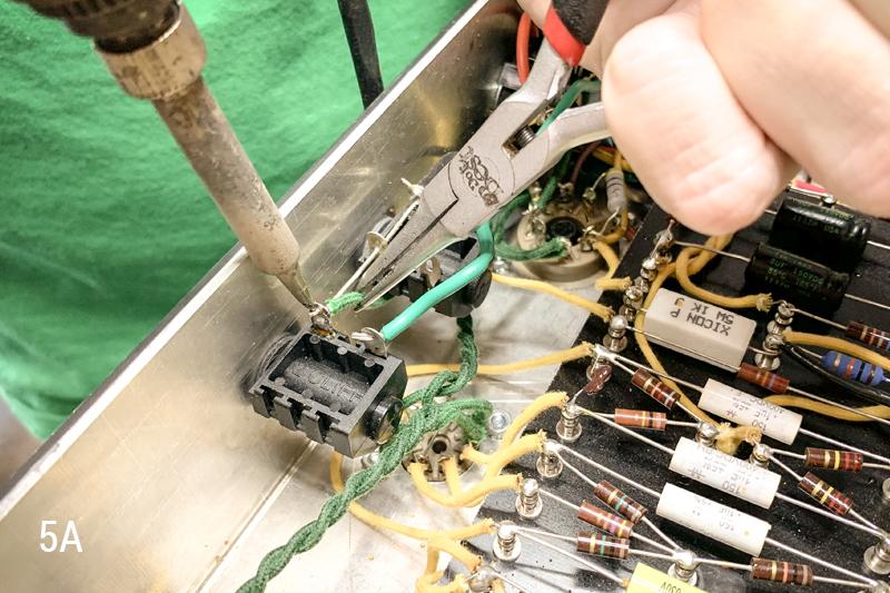
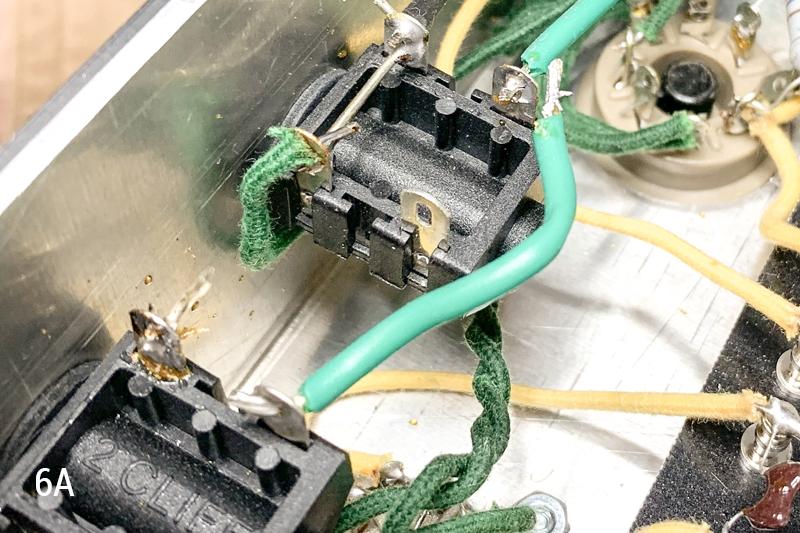
Note: If you have a ground wire running to one of the lugs on your speaker extension jack, this wire will need to be removed, and re-soldered to one of the ground lugs on your other speaker jack. See Images 5A and 6A below…
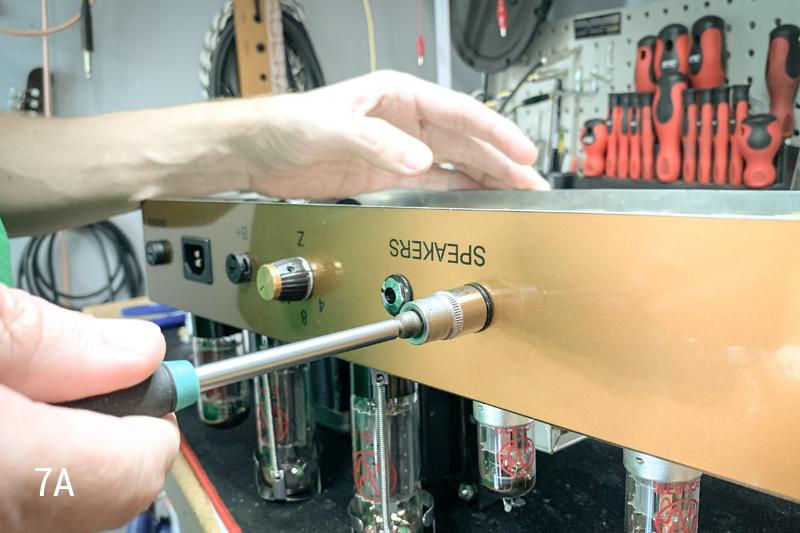
At this point, we want to remove the speaker extension jack itself to make room for the new master volume potentiometer. We have just finished removing the wires from this jack, so it should be free from any internal connections. Let’s grab a 7/16” nut driver and loosen the jack nut. See Image 7A below....
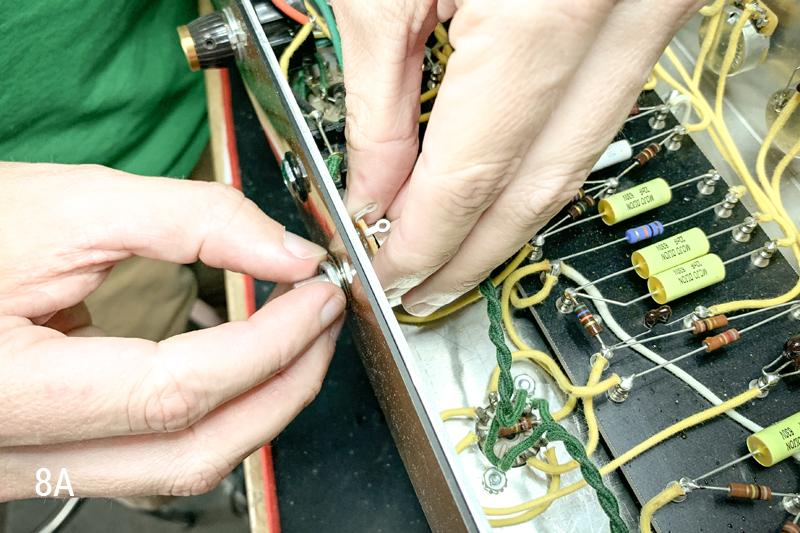
Next we need to insert the 1M volume pot, for our mod, into the now empty hole from the speaker extension jack. Insert the potentiometer with the lugs facing up towards you, as seen in Image 8A below…
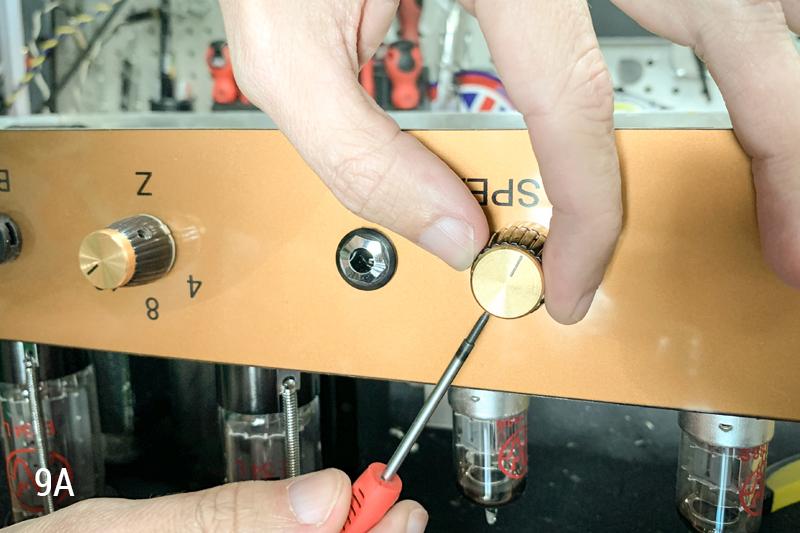
Using a ½” nut driver, tighten down the potentiometer’s nut to secure it in place. Once the pot is secured, we can go ahead and put the knob on the shaft of the pot. Make sure the potentiometer shaft is turned all the way counter-clockwise, and then slide the knob over top of the shaft with the indicator line at around 1 o’clock. Use your small flathead screwdriver to tighten down the knob’s set screw, while holding the knob in position. See Image 9A below…
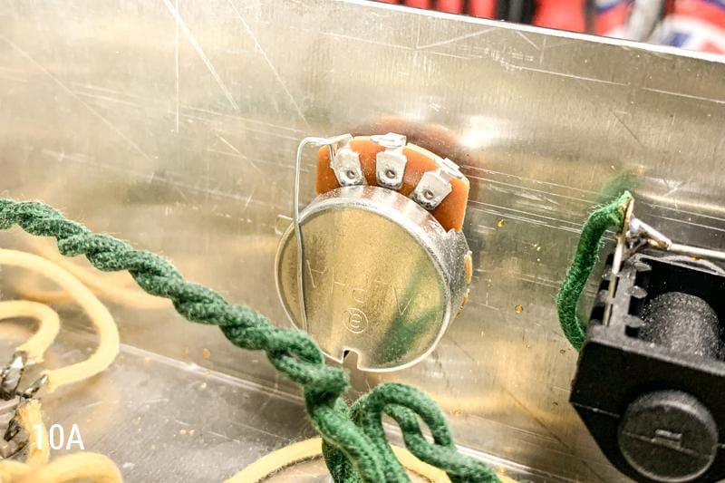
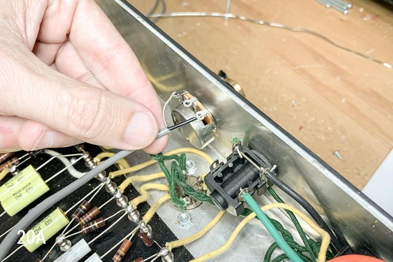
Now we need to ground our new master volume pot. Use a piece of the wire you removed from the chassis earlier to make this connection. The wire will need to run from the pot’s ground lug, to the back of the potentiometer itself. It will be helpful to use a piece of sandpaper to scuff up a portion of the back of the pot so that this solder connection can be made more easily. See Image 10A below…
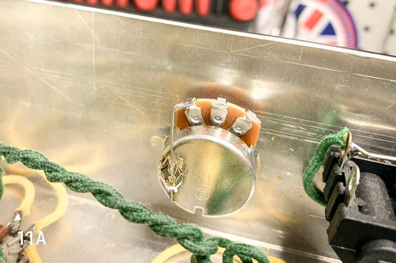
Now you’re ready to heat the contact points (one at a time) and apply solder. Once you’ve done this, your pot will be grounded. The result should look similar to Image 11A below…
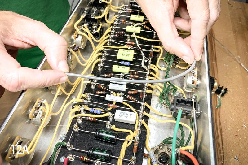
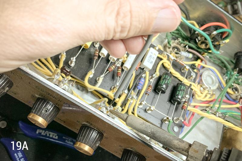
Next, we need to use the wire that came with our British 45 Master Volume Mod Kit to make a connection from the center lug on our treble potentiometer, to the lug on our master volume pot that is closest to the speaker jack. First, let’s hand-measure the length of wire we’ll need by simply running it from one connection point to the other. See Image 12A…
Then we will need to prepare our wire by stripping each end in a different way. The end connecting to the treble pot, will need to be stripped as follows:
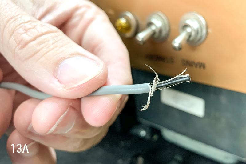
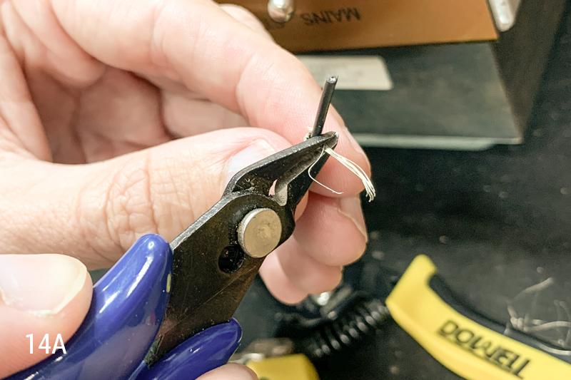
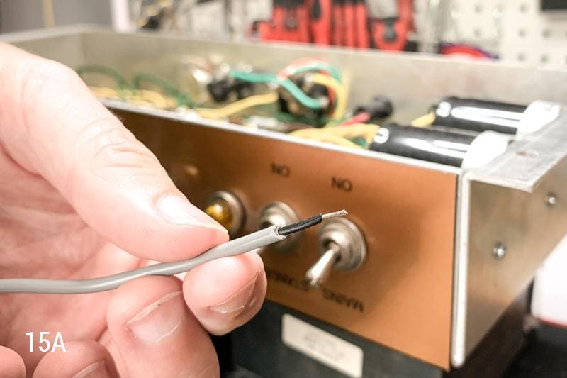
Start by gently stripping away JUST the grey outer insulation. Take it easy here, so as not to cut into the stranded wire inside. Next, cut away the bare stranded wire surrounding the black internal wire. Lastly, strip away the black insulation from the internal conductor wire. Follow the steps outlined in Images 13A - 15A…
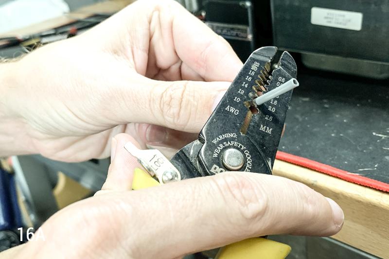
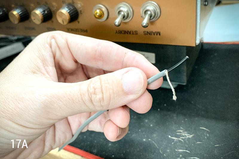
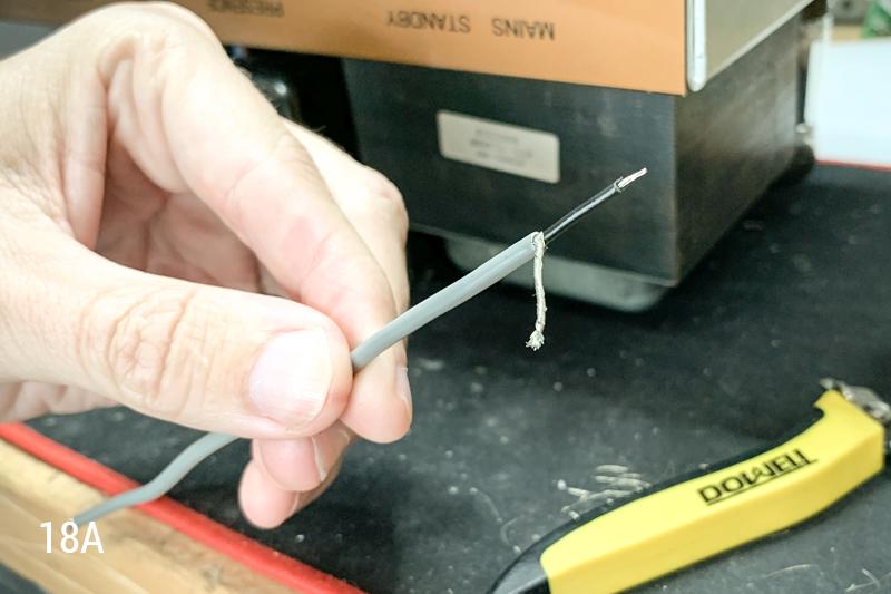
To prepare the side of the wire that will be connecting to your new master volume pot, you will need to strip away the grey exterior insulation just as before; without damaging the bare stranded wire underneath. This time, instead of cutting away the excess stranded wire, you will need to pull it all to one side and twist it together. Finally, you will strip the black internal insulation away from the conductor. Follow the steps in Images 16A - 18A…
Now it’s time to make a couple of solder connections. First, insert the side of your wire that was prepared for the treble pot, into the center lug on the treble pot and solder it in place…
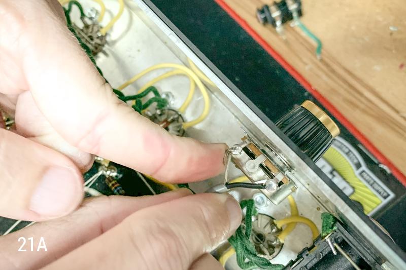
Next up, insert the side of the wire that was prepared for the master volume pot into the lug closest to the speaker jack. This will be the part of the wire within the inner most black insulation. You can go ahead and solder this in place...
Last, on the master volume side, take the remaining stranded wires and wrap them around the pot’s ground lug but do NOT solder yet…
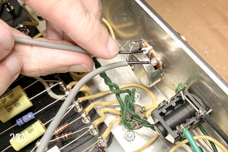
Once this is all done, we need to wire the other side of this connection; this wire will run from the board at the input to the phase inverter (where we removed our wire at the beginning) to the new master volume pot. To do this, prepare the wire exactly as we did in the previous steps: with one side stripped and prepared as it was for the treble pot (this time it will go to the input on the phase inverter), and the other side stripped and prepared as it was for the master volume pot (this, again, will go to the master volume pot).
After you’ve prepared the wires, start by making the connections on the master volume side. The innermost conductor will go to the center lug on the master volume pot. Go ahead and solder this in…
Next, take the remaining stranded wire and wrap it around the ground lug on the master volume pot, just as we did last time. This time, however, you can solder both of those stranded wires together with the ground lug on the master volume pot…

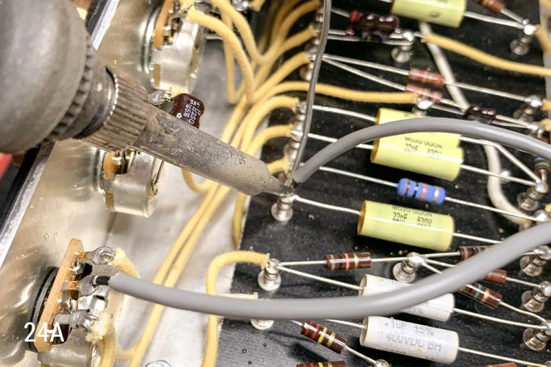
Ready for the final step? This is it! Just insert the other end of the wire into the eyelet for the input of the phase inverter and solder it into place…
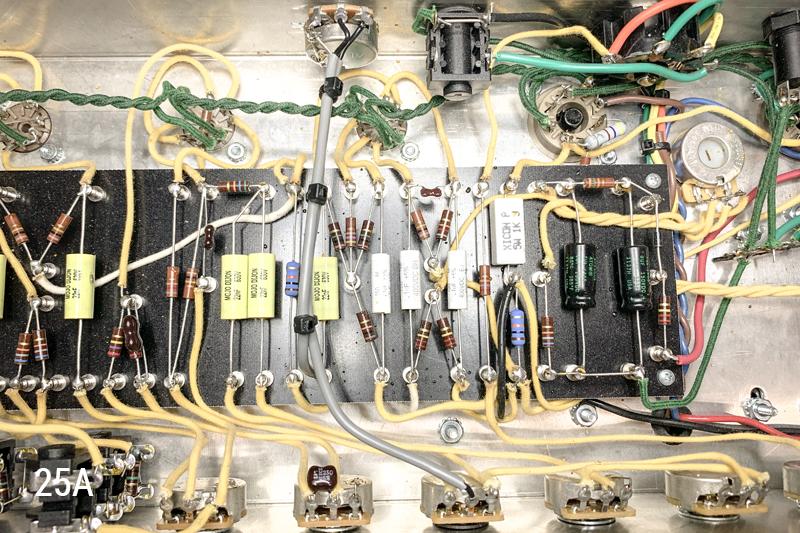
That’s it! It took a lot of pictures but we made it happen nonetheless! And now you have a killer amp that will get nice and hairy without having to be dimed. We used a couple ties to hold our wires together and keep everything nice and neat. This is not a requirement, but it does look good! In the end, your chassis should look something like this...
Now go crank the preamp, dial down the master volume and shred away without getting the cops called! Check out the sound clips below to see what ours sounds like now...
Woo! Alright, thanks for tuning in. Please let us know how your Master Volume Mods turn out. See you next time.
To make it easy, we’ve created a British 45 Master Volume Mod Kit which consists of all the parts you’ll need to complete this modification. And honestly, there are only three actual parts you’ll need: (1) 1M Potentiometer, (1) British Style Knob, and (3) Feet of wire. On a slightly more technical level, what we are doing is placing an additional volume control between the preamp and power amp by replacing the speaker extension jack with the mod kit itself.
Here’s a quick list of things you’ll need to get the job done:
British 45 Master Volume Mod KitSoldering IronSolderWire StrippersNeedle Nose PliersNut DriverSmall Flathead Screwdriver
Before we get started, we’ll need to remove our chassis from its cabinet and get it onto our work bench. Next, as always, let’s drain our filter caps for the sake of safety. If you are unfamiliar with this procedure, please check out our article outlining Filter Cap Drainage Procedures before proceeding.
Okay now that we’re super safe, let’s dive in. First, we will need to remove the wire that runs from the middle lug on the treble control pot to the input capacitor on the phase inverter. These points are outlined in Images 1A and 2A below…
Grab your needle nose pliers and your soldering iron, heat up the contact on the potentiometer, and pull the wire away. Then repeat this on the other end of the wire.
Next, it’s time to remove the two wires that run between your speaker jacks on the backside of the chassis. Take a look at Images 3A and 4A below for a visual…
To remove these wires you can heat the contact points and pull them out with your pliers, as we did earlier. In some cases you may be able to use wire cutters to simply trim these wires out.
Note: If you have a ground wire running to one of the lugs on your speaker extension jack, this wire will need to be removed, and re-soldered to one of the ground lugs on your other speaker jack. See Images 5A and 6A below…
At this point, we want to remove the speaker extension jack itself to make room for the new master volume potentiometer. We have just finished removing the wires from this jack, so it should be free from any internal connections. Let’s grab a 7/16” nut driver and loosen the jack nut. See Image 7A below....
Next we need to insert the 1M volume pot, for our mod, into the now empty hole from the speaker extension jack. Insert the potentiometer with the lugs facing up towards you, as seen in Image 8A below…
Using a ½” nut driver, tighten down the potentiometer’s nut to secure it in place. Once the pot is secured, we can go ahead and put the knob on the shaft of the pot. Make sure the potentiometer shaft is turned all the way counter-clockwise, and then slide the knob over top of the shaft with the indicator line at around 1 o’clock. Use your small flathead screwdriver to tighten down the knob’s set screw, while holding the knob in position. See Image 9A below…
Now we need to ground our new master volume pot. Use a piece of the wire you removed from the chassis earlier to make this connection. The wire will need to run from the pot’s ground lug, to the back of the potentiometer itself. It will be helpful to use a piece of sandpaper to scuff up a portion of the back of the pot so that this solder connection can be made more easily. See Image 10A below…
Now you’re ready to heat the contact points (one at a time) and apply solder. Once you’ve done this, your pot will be grounded. The result should look similar to Image 11A below…
Next, we need to use the wire that came with our British 45 Master Volume Mod Kit to make a connection from the center lug on our treble potentiometer, to the lug on our master volume pot that is closest to the speaker jack. First, let’s hand-measure the length of wire we’ll need by simply running it from one connection point to the other. See Image 12A…
Then we will need to prepare our wire by stripping each end in a different way. The end connecting to the treble pot, will need to be stripped as follows:
Start by gently stripping away JUST the grey outer insulation. Take it easy here, so as not to cut into the stranded wire inside. Next, cut away the bare stranded wire surrounding the black internal wire. Lastly, strip away the black insulation from the internal conductor wire. Follow the steps outlined in Images 13A - 15A…
To prepare the side of the wire that will be connecting to your new master volume pot, you will need to strip away the grey exterior insulation just as before; without damaging the bare stranded wire underneath. This time, instead of cutting away the excess stranded wire, you will need to pull it all to one side and twist it together. Finally, you will strip the black internal insulation away from the conductor. Follow the steps in Images 16A - 18A…
Now it’s time to make a couple of solder connections. First, insert the side of your wire that was prepared for the treble pot, into the center lug on the treble pot and solder it in place…
Next up, insert the side of the wire that was prepared for the master volume pot into the lug closest to the speaker jack. This will be the part of the wire within the inner most black insulation. You can go ahead and solder this in place...
Last, on the master volume side, take the remaining stranded wires and wrap them around the pot’s ground lug but do NOT solder yet…
Once this is all done, we need to wire the other side of this connection; this wire will run from the board at the input to the phase inverter (where we removed our wire at the beginning) to the new master volume pot. To do this, prepare the wire exactly as we did in the previous steps: with one side stripped and prepared as it was for the treble pot (this time it will go to the input on the phase inverter), and the other side stripped and prepared as it was for the master volume pot (this, again, will go to the master volume pot).
After you’ve prepared the wires, start by making the connections on the master volume side. The innermost conductor will go to the center lug on the master volume pot. Go ahead and solder this in…
Next, take the remaining stranded wire and wrap it around the ground lug on the master volume pot, just as we did last time. This time, however, you can solder both of those stranded wires together with the ground lug on the master volume pot…
Ready for the final step? This is it! Just insert the other end of the wire into the eyelet for the input of the phase inverter and solder it into place…
That’s it! It took a lot of pictures but we made it happen nonetheless! And now you have a killer amp that will get nice and hairy without having to be dimed. We used a couple ties to hold our wires together and keep everything nice and neat. This is not a requirement, but it does look good! In the end, your chassis should look something like this...
Now go crank the preamp, dial down the master volume and shred away without getting the cops called! Check out the sound clips below to see what ours sounds like now...
Woo! Alright, thanks for tuning in. Please let us know how your Master Volume Mods turn out. See you next time.