Welcome back to the final installment of our 5E3 Style Amp Kit Build. In this episode we will go over how to wire up the speaker wiring harness, install the 12" speaker, and mount the chassis into the cabinet. So let's get to it!
For our wiring harness we will need a soldering iron, a tiny bit of solder, and a small phillips head screw driver. For the speaker and chassis installation, we will need a few small nut drivers (I just grabbed whatever I had around...hope they work!) or a small adjustable wrench, as well as an electric drill or a regular phillips head screw driver. We've reached the easy part so this is really all we are going to need.
Note : Before completing these steps, it is best to test your amp using a multimeter to make sure the right points are getting the right amount of voltage. Failure to do this could result in damage to your circuit if anything happens to be open or short. We outlined the testing points for this amp in a separate article as part of our Fix It Friday series -- please click the following link for more info on testing: 5E3 Test Points
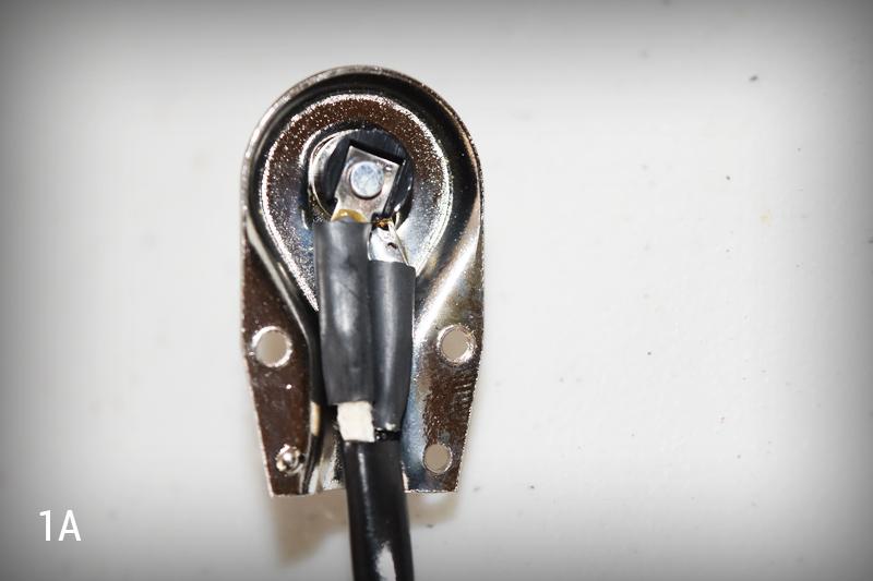
First let's get our speaker wiring harness soldered up and ready to go. We need to use our small phillips head screw driver to remove the screws on the back of the included right angle jack. Once we've done this, we can push back the cloth on our white wire and solder it to the center lug inside the jack. Once this is done, we need to solder our black wire straight onto the metal shield for grounding (See Image 1A). You'll notice I added some heat sink to the ends of my wires -- this is not required, I just get a little particular sometimes.
I like to twist my wires together after they are soldered to the jack -- this just gives a nice clean look. Now that we are here, let's set our harnesses aside for a moment while we install the speaker...
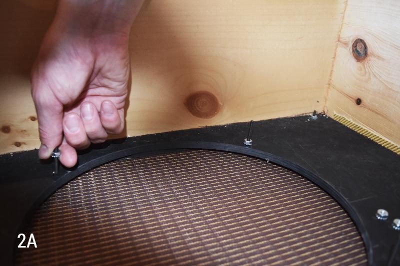
At this point, you will need to go ahead and remove both the top and bottom back panels with our drill or screw drivers. Then, we can unscrew the locknuts that are on the speaker mounting screws (See Image 2A).
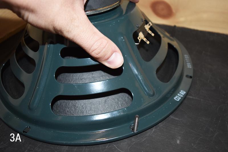
Next, we must carefully align the holes on the outer rim of our speaker with the mounting screws in our baffle. We can then begin to slowly work the speaker down until it is seated right down against the baffle (See Image 3A). Note : The paper that sits overtop the speaker mounting holes will tear a little during this process -- this is completely normal and harmless to the speaker, just take your time and everything should seat properly with no issue.
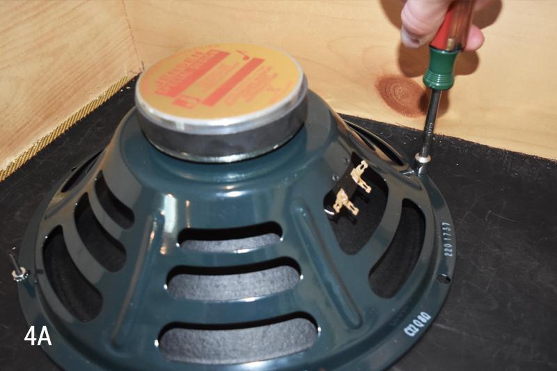
Now we need to reapply the locknuts to fasten our speaker in place -- let's grab a nut driver an get them on. We want to tighten these nuts enough to be secure but not so much that we bend the speaker frame (See Image 4A).
Okay, so now our speaker is installed -- this is a good time to go ahead and solder the harness to the speaker. You know the drill, black wire goes to negative, and white wire goes to positive -- find the terminals, push the cloth back on your wire, and solder them up!
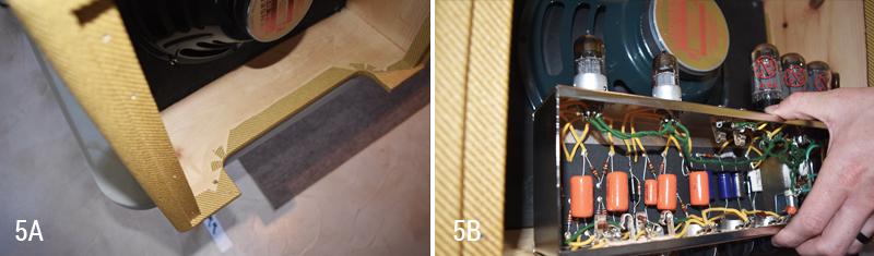
Now we need to get our chassis in there. The way I like to do this is to actually place the cabinet upside down on my work area, and let the curved chassis cutout hang over the edge of my work surface (See Image 5A). Then I place the chassis into the cabinet with the knobs facing downward, so the component board is facing me (Image 5B).
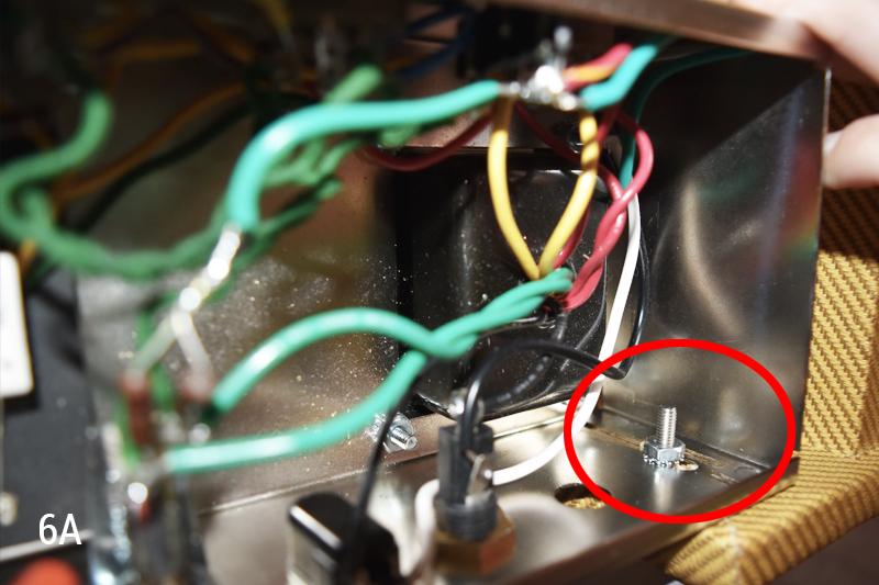
Now, align the mounting holes in your chassis with the mounting holes in your cabinet, and insert the included chassis mounting screws in (one at a time). First through the cabinet and then up through the chassis mounting holes, and then hand-tighten the locknut on (See Image 6A). Note : Only hand tighten as a place holder at this time -- we need to make sure the chassis is in the right position before we do the final tightening.
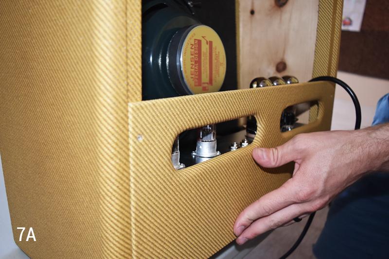
In order to make sure our chassis in oriented properly from front to back in our cabinet, let's put our top back panel into it's place and press the chassis into it (See Image 7A). This will ensure our chassis is flush against our backpanel and that there is no noticeable gap between the two. Once this is done, hold your chassis right where it is and finish tightening the locknuts down onto the screws.
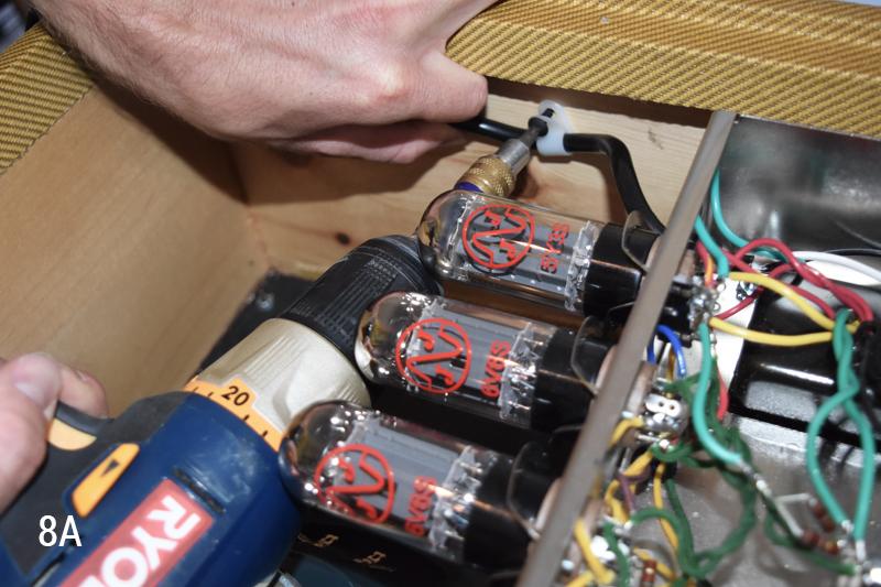
One little finishing touch I'm going to do today is the installation of the strain relief. This is the little white plastic c-clamp looking number that came with your kit. The purpose of this is to take tension off of the actual power inlet so your power cord lasts longer through all your gigging and practicing, etc. All we need to do is grab our little white strain relief, place the power cable into it, and then screw the included wood screw into the side of the cabinet to displace the tension on the cord (See Image 8A).
Now all that' left to do is reinstall our back panels, turn her on, and crank! Thank you guys so much for joining us -- this project has been a ton of fun and a huge learning experience for me, so I hope it was for you as well. We are going to be doing more fun projects like this in the near future so please keep following along! And check the video below for a quick sound demo!
For our wiring harness we will need a soldering iron, a tiny bit of solder, and a small phillips head screw driver. For the speaker and chassis installation, we will need a few small nut drivers (I just grabbed whatever I had around...hope they work!) or a small adjustable wrench, as well as an electric drill or a regular phillips head screw driver. We've reached the easy part so this is really all we are going to need.
Note : Before completing these steps, it is best to test your amp using a multimeter to make sure the right points are getting the right amount of voltage. Failure to do this could result in damage to your circuit if anything happens to be open or short. We outlined the testing points for this amp in a separate article as part of our Fix It Friday series -- please click the following link for more info on testing: 5E3 Test Points
First let's get our speaker wiring harness soldered up and ready to go. We need to use our small phillips head screw driver to remove the screws on the back of the included right angle jack. Once we've done this, we can push back the cloth on our white wire and solder it to the center lug inside the jack. Once this is done, we need to solder our black wire straight onto the metal shield for grounding (See Image 1A). You'll notice I added some heat sink to the ends of my wires -- this is not required, I just get a little particular sometimes.
I like to twist my wires together after they are soldered to the jack -- this just gives a nice clean look. Now that we are here, let's set our harnesses aside for a moment while we install the speaker...
At this point, you will need to go ahead and remove both the top and bottom back panels with our drill or screw drivers. Then, we can unscrew the locknuts that are on the speaker mounting screws (See Image 2A).
Next, we must carefully align the holes on the outer rim of our speaker with the mounting screws in our baffle. We can then begin to slowly work the speaker down until it is seated right down against the baffle (See Image 3A). Note : The paper that sits overtop the speaker mounting holes will tear a little during this process -- this is completely normal and harmless to the speaker, just take your time and everything should seat properly with no issue.
Now we need to reapply the locknuts to fasten our speaker in place -- let's grab a nut driver an get them on. We want to tighten these nuts enough to be secure but not so much that we bend the speaker frame (See Image 4A).
Okay, so now our speaker is installed -- this is a good time to go ahead and solder the harness to the speaker. You know the drill, black wire goes to negative, and white wire goes to positive -- find the terminals, push the cloth back on your wire, and solder them up!
Now we need to get our chassis in there. The way I like to do this is to actually place the cabinet upside down on my work area, and let the curved chassis cutout hang over the edge of my work surface (See Image 5A). Then I place the chassis into the cabinet with the knobs facing downward, so the component board is facing me (Image 5B).
Now, align the mounting holes in your chassis with the mounting holes in your cabinet, and insert the included chassis mounting screws in (one at a time). First through the cabinet and then up through the chassis mounting holes, and then hand-tighten the locknut on (See Image 6A). Note : Only hand tighten as a place holder at this time -- we need to make sure the chassis is in the right position before we do the final tightening.
In order to make sure our chassis in oriented properly from front to back in our cabinet, let's put our top back panel into it's place and press the chassis into it (See Image 7A). This will ensure our chassis is flush against our backpanel and that there is no noticeable gap between the two. Once this is done, hold your chassis right where it is and finish tightening the locknuts down onto the screws.
One little finishing touch I'm going to do today is the installation of the strain relief. This is the little white plastic c-clamp looking number that came with your kit. The purpose of this is to take tension off of the actual power inlet so your power cord lasts longer through all your gigging and practicing, etc. All we need to do is grab our little white strain relief, place the power cable into it, and then screw the included wood screw into the side of the cabinet to displace the tension on the cord (See Image 8A).
Now all that' left to do is reinstall our back panels, turn her on, and crank! Thank you guys so much for joining us -- this project has been a ton of fun and a huge learning experience for me, so I hope it was for you as well. We are going to be doing more fun projects like this in the near future so please keep following along! And check the video below for a quick sound demo!