Welcome, and thank you for joining us on this wonderful Make It Monday! Today, we are going to take a bit of a step back and address some very basic, but extremely valuable build processes.
Cables are really the unsung heroes of our rigs; without them, our sound would have no way to get from point A to point B. There are a lot of great cable companies on the market, and yes some of them do actually make a product that's higher quality than others, but we all know buying those brand name cables can be expensive. Additionally, if you’re reading this, you’re obviously on a quest to be as self-sufficient as possible, so why not learn how to properly wire up your own cables? Let’s take a look at three commonly used (and commonly replaced) types of cables: Speaker Cable, Instrument Cable, and RCA Cable.
Note : I’ll show you the basics on these bad boys using some affordable Mojotone products and very few tools. In my demonstrations, I’ll only be using a foot of cable for each application, but your needs will likely vary from mine so make sure you know how much cable you’ll need/want before getting started. I’ll also be using standard ¼” jacks for my speaker and instrument cable but your needs may vary there as well.
Here is a list of the tools and supplies we’ll need for this project:
Wire StrippersWire CuttersSoldering IronSolder18-Ga Speaker Cable24-Ga Instrument CableVintage External Braid Reverb WireVintage Style Male RCA Phono Plugs¼” 2-conductor Mono Phone Plugs (Male)
Starting with our 18-Ga speaker cable, we first need to cut the cable down to whatever length is necessary for this application. Again, I’m demonstrating on a foot of wire so my cables have already been cut to length. Next let’s place our cable into the strain relief of the plug to get a visual idea of how far back we’ll need to strip our insulation (Image 1A).

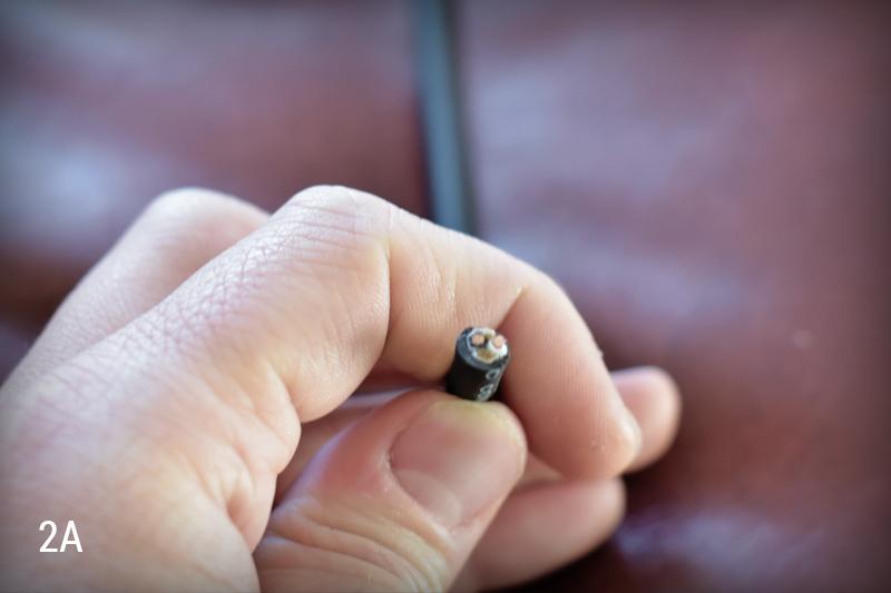
As we can see, there is close to a half inch of insulation that need to be stripped between the end of the interior side of the strain relief and the contacts for our solder joints. If you look inside the cable, you’ll notice two wires (black and white) that each have their own insulation (Image 2A).
We need to strip the external insulation back without puncturing the insulation on the internal black and white wires. I’ll be using a set of wire strippers with a blade edge on them -- some people like to simply use a fresh razor blade in this scenario. See the short video clip below…
Upon stripping the external insulation, you’ll notice a few pieces of non-conductive fibrous material -- these can be cut down to get them out of the way, as we are only interested in the black and white insulated wires. Next, we need to strip back the insulation on our black and white wires, but we only need to strip enough of it to make a good solder connection.
Note : Often times a cable can go bad if the black and/or white wire is stripped too far back as this leaves the wire exposed and increases the potential for the wire to make contact with other conductive parts.
I’m going to use my wire strippers to strip just the right amount without damaging the wire itself…
Now it’s time to prepare our wires as well as the pins on our plug for soldering, by tinning them. Tinning is another word for applying just a little bit of solder to the surfaces so that they come together more smoothly. We’ll start by lightly tinning our black and white wires, and then we’ll move on to the hot pin and shield on our ¼” plug…
Alright, you know what to do now. Make sure your soldering iron is nice and warm and then go ahead and seat the cable into the strain relief on the plug and orient the wires accordingly. The white wire will go to the plug’s hot pin, and the black wire will go to the shield (Image 4A).

Since we’ve tinned our components, we will need to use just the slightest bit of solder. So heat the wire and the contact, drop a touch of solder on, and then remove from heat to allow the joint to cool briefly…
Now we need to tighten down the strain relief clamps. I’ll be doing this with my wire strippers but one could also use pliers…
Finally, we’ll need to slide the included plastic insulation sleeve over the wires and up to the threads on the plug. Then, we’ll do the same with the metal housing, and twist to fasten it down to the plug…
Repeat these steps on the other end of the cable and you’ll have yourself a well-built, well-insulated speaker cable!
The instrument cable is very similar to the speaker cable in that there are two conductors that need to be soldered. However, instead of two independently insulated conductors, one black and one white, the instrument cable has an insulated center conductor wrapped in shield wire. This shield wire will need to be twisted together and soldered to the shield of the plug.
Let’s start the same way we did with the speaker cable: place the cable into the strain relief of the plug to get a visual idea of how much insulation to strip back. Once you know how much to strip back, use your cutters or razor blade to delicately strip the external insulation back without puncturing the internal shield wire or insulated wire. Once this is done, we’ll need to twist the exposed shield wire together to make an actual solderable wire (Image 5A).

Next, we need to strip back the insulation on that small center wire (this will be our hot wire). You may notice that underneath the black rubber insulation there is another layer of clear insulation -- we need to remove both of these. Here again, remove just enough of the insulation to make good contact with the plug. The end result should look like Image 6A below…

Once again, we will need to tin the wires as well as the hot pin and shield on the plug. This will make our lives easier in the end. As a refresher, we’ve included the same video clips from the above section on speaker cable wiring…
From here on out, the process is essentially identical to that of the above speaker cable demonstration. Slide the metal housing over the wires and onto the cable, then do the same with the included plastic insulation sleeve. Next, get the wires where they need to be -- the insulated center wire will go to the hot pin on the plug, and the hand-twisted shield wire will go to the plug’s shield. Once you’re comfortable with how things are seated, go ahead and solder the wires in and let them cool for a second. Finally, clip any excess wire, slide the plastic sleeve over the wires and up to the threads on the plug, and then slide the metal housing over the plastic sleeve and twist it to fasten it to the plug. (See examples from the above section on speaker cable wiring)
Now that you know how to wire up your own speaker cables and instrument cables, let’s move on to something slightly less common in the pro audio world, but still quite crucial especially when it comes to vintage amps: the vintage-style RCA cable.
The vintage-style RCA cables will be made using a vintage style RCA plug with a hot pin and a shield, as well as a external braid reverb wire. This wire consists of an external braided shield (which will be wired to the shield on the plug) and an insulated internal wire (this is a stranded wire that will need to be twisted together and wired to the plug’s hot pin). Making this RCA cable involves less prep work as we won’t be pre-tinning anything, but the way in which the cable is ultimately wired is a little bit unexpected.
Let’s start by getting our wire ready. To do this, we will need to strip back about a half inch of the external braid using our wire strippers. Next up, we’ll need to strip back the insulation surrounding the internal hot wire by about a half inch -- be mindful so as not to puncture the hot wire itself. Now, simply twist the stranded wire together (by hand) as tight as possible. Once we’ve stripped both of these parts back and twisted the stranded hot wire, we should be left with something resembling Image 7A below…

Set your wire aside for the time being and let’s turn our focus towards the plug. You’ll notice the plug consists of a wide metal shield and a long thin hot pin protruding from the center of the shield. The only viable solder point for the hot wire and pin is actually at the very tip of the hot pin where you’ll notice a small hole. Take a look at Image 8A below for a visual break down…

With this solder point in mind, we must actually insert the hot wire all the way up through the bottom of the hot pin and out the hollow tip. It’s best to leave some excess wire hanging out of the tip of the hot pin until after we’ve soldered (Image 9A).

Note : You’ll likely notice that getting the wire through the tip of the hot pin is already a tight squeeze -- this is why we did not pre-tin our wire. Often times people are unable to get the wire through at all after tinning the wire, which makes it extremely difficult to solder!
You’ll also notice in my image above, that I did not allow the braided shield to follow the other wire into the hole on the bottom of the plug. This is because we will eventually need to solder the braided shield to the bottom of the shield itself.
For now, let’s get this hot pin soldered in. Grab a hot soldering iron, heat the tip of the pin and the excess wire protruding from the top, and apply just a dab of solder...
Once we’re soldered in, we need to just use our wire clippers to get rid of that excess wire hanging out the top of our plug. Then we can move on to wiring the shield. The way to do this is to simply push the braided shield wire up against the shield of the plug and hold it there while you solder. This can be a bit odd so it may take a trial or two the first time you go at it, but we are really just soldering the braided wire to the outside of the plug any way we can. See Images 10A and 10B below.

Mine didn’t turn out quite as pretty as I’d hoped but it has a clean and solid connection one way or another, and that’s the important part. Now we can repeat this process on the other end of the cable and we’ll have ourselves a working homemade RCA cable!
We really appreciate you tuning in today. We are always looking for article ideas so if you find yourself really wanting to see a Make It Monday or Fix It Friday article on a certain topic, please feel encouraged to send any and all suggestions to logan@mojotone.com. Take care and we’ll see you next time!
Cables are really the unsung heroes of our rigs; without them, our sound would have no way to get from point A to point B. There are a lot of great cable companies on the market, and yes some of them do actually make a product that's higher quality than others, but we all know buying those brand name cables can be expensive. Additionally, if you’re reading this, you’re obviously on a quest to be as self-sufficient as possible, so why not learn how to properly wire up your own cables? Let’s take a look at three commonly used (and commonly replaced) types of cables: Speaker Cable, Instrument Cable, and RCA Cable.
Note : I’ll show you the basics on these bad boys using some affordable Mojotone products and very few tools. In my demonstrations, I’ll only be using a foot of cable for each application, but your needs will likely vary from mine so make sure you know how much cable you’ll need/want before getting started. I’ll also be using standard ¼” jacks for my speaker and instrument cable but your needs may vary there as well.
Here is a list of the tools and supplies we’ll need for this project:
Wire StrippersWire CuttersSoldering IronSolder18-Ga Speaker Cable24-Ga Instrument CableVintage External Braid Reverb WireVintage Style Male RCA Phono Plugs¼” 2-conductor Mono Phone Plugs (Male)
SPEAKER CABLE
Starting with our 18-Ga speaker cable, we first need to cut the cable down to whatever length is necessary for this application. Again, I’m demonstrating on a foot of wire so my cables have already been cut to length. Next let’s place our cable into the strain relief of the plug to get a visual idea of how far back we’ll need to strip our insulation (Image 1A).
As we can see, there is close to a half inch of insulation that need to be stripped between the end of the interior side of the strain relief and the contacts for our solder joints. If you look inside the cable, you’ll notice two wires (black and white) that each have their own insulation (Image 2A).
We need to strip the external insulation back without puncturing the insulation on the internal black and white wires. I’ll be using a set of wire strippers with a blade edge on them -- some people like to simply use a fresh razor blade in this scenario. See the short video clip below…
Note : Often times a cable can go bad if the black and/or white wire is stripped too far back as this leaves the wire exposed and increases the potential for the wire to make contact with other conductive parts.
I’m going to use my wire strippers to strip just the right amount without damaging the wire itself…
Now it’s time to prepare our wires as well as the pins on our plug for soldering, by tinning them. Tinning is another word for applying just a little bit of solder to the surfaces so that they come together more smoothly. We’ll start by lightly tinning our black and white wires, and then we’ll move on to the hot pin and shield on our ¼” plug…
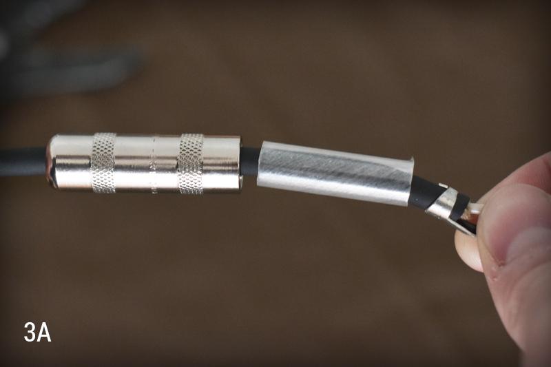
After we’ve applied just a little bit of solder to our wires and plug, we are ready to solder everything together. However, before soldering, let’s go ahead and slide the plug’s metal housing over the wires and onto the cable, and then do the same with the included plastic insulation sleeve (See Image 3A Below). If we fail to get these items onto the cable first, we will soon realize that we are unable to slide the metal housing on from the opposite direction...and then we might start using bad words.
Alright, you know what to do now. Make sure your soldering iron is nice and warm and then go ahead and seat the cable into the strain relief on the plug and orient the wires accordingly. The white wire will go to the plug’s hot pin, and the black wire will go to the shield (Image 4A).
Since we’ve tinned our components, we will need to use just the slightest bit of solder. So heat the wire and the contact, drop a touch of solder on, and then remove from heat to allow the joint to cool briefly…
Now we need to tighten down the strain relief clamps. I’ll be doing this with my wire strippers but one could also use pliers…
Finally, we’ll need to slide the included plastic insulation sleeve over the wires and up to the threads on the plug. Then, we’ll do the same with the metal housing, and twist to fasten it down to the plug…
Repeat these steps on the other end of the cable and you’ll have yourself a well-built, well-insulated speaker cable!
INSTRUMENT CABLE
The instrument cable is very similar to the speaker cable in that there are two conductors that need to be soldered. However, instead of two independently insulated conductors, one black and one white, the instrument cable has an insulated center conductor wrapped in shield wire. This shield wire will need to be twisted together and soldered to the shield of the plug.
Let’s start the same way we did with the speaker cable: place the cable into the strain relief of the plug to get a visual idea of how much insulation to strip back. Once you know how much to strip back, use your cutters or razor blade to delicately strip the external insulation back without puncturing the internal shield wire or insulated wire. Once this is done, we’ll need to twist the exposed shield wire together to make an actual solderable wire (Image 5A).
Next, we need to strip back the insulation on that small center wire (this will be our hot wire). You may notice that underneath the black rubber insulation there is another layer of clear insulation -- we need to remove both of these. Here again, remove just enough of the insulation to make good contact with the plug. The end result should look like Image 6A below…
Once again, we will need to tin the wires as well as the hot pin and shield on the plug. This will make our lives easier in the end. As a refresher, we’ve included the same video clips from the above section on speaker cable wiring…
From here on out, the process is essentially identical to that of the above speaker cable demonstration. Slide the metal housing over the wires and onto the cable, then do the same with the included plastic insulation sleeve. Next, get the wires where they need to be -- the insulated center wire will go to the hot pin on the plug, and the hand-twisted shield wire will go to the plug’s shield. Once you’re comfortable with how things are seated, go ahead and solder the wires in and let them cool for a second. Finally, clip any excess wire, slide the plastic sleeve over the wires and up to the threads on the plug, and then slide the metal housing over the plastic sleeve and twist it to fasten it to the plug. (See examples from the above section on speaker cable wiring)
RCA CABLES
Now that you know how to wire up your own speaker cables and instrument cables, let’s move on to something slightly less common in the pro audio world, but still quite crucial especially when it comes to vintage amps: the vintage-style RCA cable.
The vintage-style RCA cables will be made using a vintage style RCA plug with a hot pin and a shield, as well as a external braid reverb wire. This wire consists of an external braided shield (which will be wired to the shield on the plug) and an insulated internal wire (this is a stranded wire that will need to be twisted together and wired to the plug’s hot pin). Making this RCA cable involves less prep work as we won’t be pre-tinning anything, but the way in which the cable is ultimately wired is a little bit unexpected.
Let’s start by getting our wire ready. To do this, we will need to strip back about a half inch of the external braid using our wire strippers. Next up, we’ll need to strip back the insulation surrounding the internal hot wire by about a half inch -- be mindful so as not to puncture the hot wire itself. Now, simply twist the stranded wire together (by hand) as tight as possible. Once we’ve stripped both of these parts back and twisted the stranded hot wire, we should be left with something resembling Image 7A below…
Set your wire aside for the time being and let’s turn our focus towards the plug. You’ll notice the plug consists of a wide metal shield and a long thin hot pin protruding from the center of the shield. The only viable solder point for the hot wire and pin is actually at the very tip of the hot pin where you’ll notice a small hole. Take a look at Image 8A below for a visual break down…
With this solder point in mind, we must actually insert the hot wire all the way up through the bottom of the hot pin and out the hollow tip. It’s best to leave some excess wire hanging out of the tip of the hot pin until after we’ve soldered (Image 9A).
Note : You’ll likely notice that getting the wire through the tip of the hot pin is already a tight squeeze -- this is why we did not pre-tin our wire. Often times people are unable to get the wire through at all after tinning the wire, which makes it extremely difficult to solder!
You’ll also notice in my image above, that I did not allow the braided shield to follow the other wire into the hole on the bottom of the plug. This is because we will eventually need to solder the braided shield to the bottom of the shield itself.
For now, let’s get this hot pin soldered in. Grab a hot soldering iron, heat the tip of the pin and the excess wire protruding from the top, and apply just a dab of solder...
Once we’re soldered in, we need to just use our wire clippers to get rid of that excess wire hanging out the top of our plug. Then we can move on to wiring the shield. The way to do this is to simply push the braided shield wire up against the shield of the plug and hold it there while you solder. This can be a bit odd so it may take a trial or two the first time you go at it, but we are really just soldering the braided wire to the outside of the plug any way we can. See Images 10A and 10B below.
Mine didn’t turn out quite as pretty as I’d hoped but it has a clean and solid connection one way or another, and that’s the important part. Now we can repeat this process on the other end of the cable and we’ll have ourselves a working homemade RCA cable!
We really appreciate you tuning in today. We are always looking for article ideas so if you find yourself really wanting to see a Make It Monday or Fix It Friday article on a certain topic, please feel encouraged to send any and all suggestions to logan@mojotone.com. Take care and we’ll see you next time!