Greetings pro audio enthusiasts, and welcome to another installment of Mojotone’s Make It Monday series! Today, we’re embarking on the first leg of a two-part tutorial outlining the assembly of Mojotone’s Tweed Champ Style (or 5E1) Amplifier Kit. The 5E1 circuit is great for first time builds, but is also just an absolute classic -- the Fender Tweed Champ has been used for decades on some of the most famous recordings in history...so get your head around THAT!
We wanted to work on the Champ for two reasons: 1) It’s a necessary and fun build for this DIY community, and 2) We needed a reason to show off Mojotone’s new and improved Wiring Diagram and Build Manual! These jazzed up documents make the build process much easier and more enjoyable -- they include some detailed illustrations of the parts and a very thorough step-by-step breakdown of how to actually assemble and wire the kit.
While I won’t be able to photograph and individually demonstrate each and every step in the manual, I will be able to highlight some of the key steps in this article; the rest should be cake if you’re following along with the new Kit Build Manual.
For this first leg, you’ll need the following tools and supplies:
½” Nut DriverAdjustable WrenchPhillips Head Screw DriverSoldering IronSolderMojotone Tweed Champ Style Amp Kit
Alright, enough chit-chat, let’s dive in! A good first thing to do is to break open your small parts kit and take a quick inventory. You’ll notice upon unboxing the kit that the box includes a parts inventory list, a wiring diagram, and a schematic; go ahead and grab the inventory list and sift through the big box and the small plastic hardware box to make sure all of your components are present.
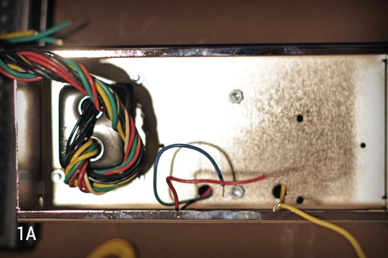
Once you’ve taken inventory, it’s time to prep the chassis by populating it with hardware. The build manual says we should start by installing the power transformer. We’ll do this by inserting the transformer’s mounting posts down into the chassis, from the top, with the black leads closest to the front panel of the chassis and the colorful leads closest to the rear panel of the chassis. Then we’ll use (4) of the included 8-32 keps nuts and our adjustable wrench to secure the transformer in place…
Next we can move on to the output transformer. Let’s insert this with the blue and red leads closer to the power transformer side of the chassis, and the single yellow lead on the opposite side. Once we’ve installed both transformers, we should be looking like Image 1A below.
Now, following our manual, we can mount the fuse holder. Simply insert the fuse holder into the appropriate cutout on the front panel of the chassis, and fasten down the included nut with your adjustable wrench…
Now comes the indicator light. Before we can mount the light fixture, we need to solder our (2) 100 ohm resistors to the light’s shield. This requires us to insert one end of each resistor into one of the holes on the lamp’s solder tabs, and twist the other two leads together (See Image 2A below).

Then all we need to do is solder the twisted ends to that bottom plate…
Before installing the indicator light onto the chassis, we can also solder the other two leads into those holes in the tab. Once this is done, simply use the included hardware to secure the indicator light fixture onto the chassis.
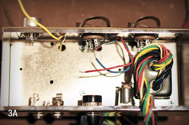
The next few steps are fairly straight-forward. These involve mounting the potentiometer, mounting the tube sockets, and mounting the input jacks. To save some time, let’s all follow along in our build manuals for a more detailed look at these steps and meet back at Image 3A below for an example of what things should look like once we’ve finished the above steps.
Our next and final group of steps for today are those outlining the initial transformer wiring. One big thing to note in this section is this: you want to make all solder connections only once. That said, if you notice a solder point in this section needs to have additional leads connected to it, do not solder it. We will only be making solder connections on points that have a single lead connected to them.
We should begin by twisting together all leads of like color on your power transformer…
Next, it’s time to run all of the transformer leads out to their connection points to get a measurement for how long they’ll need to be. Use the kit’s wiring diagram to see where each lead needs to go, run it to the corresponding point, and trim the wire to length…
After trimming the wires to their respective lengths, you’ll likely notice you now have an easier space in which to work. You’ll also be ready to identify the wires which are the only occupants of a solder point; once you’ve identified these bad boys (which should be the red wires from both your power transformer and output transformer, the black and white wires from your power transformer and ONE of the yellow wires from your power transformer), go ahead and use your wire strippers to strip back the insulation just a touch. And now, we’re ready for today’s final step...soldering in the wires we’ve just stripped. Here is a little breakdown of what we’re going to be soldering…
PT Red - Pin 4 on Rectifier Tube SocketPT Red - Pin 6 on Rectifier Tube SocketPT Black - Lug on Fuse HolderPT White - Lug on back of PotentiometerPT Yellow - Pin 2 on Rectifier Tube SocketOT Red - Pin 3 on 6V6 Tube Socket
Even though I’ve given this breakdown, it’s always best practice to follow your wiring diagram closely, so use this opportunity to practice reading your diagram. Alright, let’s get to soldering…
Yow!! We’ve done it! We have completed the first half of our Tweed Champ Style Kit Build. Wasn’t that easy? I feel good about myself and you certainly should too. Let’s take a break and meet back here next time so we can populate our fiberboards, make all of our remaining solder connections, and drop this chassis into its cabinet. Alright, we’ll see you soon -- thanks for tuning in!

We wanted to work on the Champ for two reasons: 1) It’s a necessary and fun build for this DIY community, and 2) We needed a reason to show off Mojotone’s new and improved Wiring Diagram and Build Manual! These jazzed up documents make the build process much easier and more enjoyable -- they include some detailed illustrations of the parts and a very thorough step-by-step breakdown of how to actually assemble and wire the kit.
While I won’t be able to photograph and individually demonstrate each and every step in the manual, I will be able to highlight some of the key steps in this article; the rest should be cake if you’re following along with the new Kit Build Manual.
For this first leg, you’ll need the following tools and supplies:
½” Nut DriverAdjustable WrenchPhillips Head Screw DriverSoldering IronSolderMojotone Tweed Champ Style Amp Kit
Alright, enough chit-chat, let’s dive in! A good first thing to do is to break open your small parts kit and take a quick inventory. You’ll notice upon unboxing the kit that the box includes a parts inventory list, a wiring diagram, and a schematic; go ahead and grab the inventory list and sift through the big box and the small plastic hardware box to make sure all of your components are present.
Once you’ve taken inventory, it’s time to prep the chassis by populating it with hardware. The build manual says we should start by installing the power transformer. We’ll do this by inserting the transformer’s mounting posts down into the chassis, from the top, with the black leads closest to the front panel of the chassis and the colorful leads closest to the rear panel of the chassis. Then we’ll use (4) of the included 8-32 keps nuts and our adjustable wrench to secure the transformer in place…
Next we can move on to the output transformer. Let’s insert this with the blue and red leads closer to the power transformer side of the chassis, and the single yellow lead on the opposite side. Once we’ve installed both transformers, we should be looking like Image 1A below.
Now, following our manual, we can mount the fuse holder. Simply insert the fuse holder into the appropriate cutout on the front panel of the chassis, and fasten down the included nut with your adjustable wrench…
Now comes the indicator light. Before we can mount the light fixture, we need to solder our (2) 100 ohm resistors to the light’s shield. This requires us to insert one end of each resistor into one of the holes on the lamp’s solder tabs, and twist the other two leads together (See Image 2A below).
Then all we need to do is solder the twisted ends to that bottom plate…
Before installing the indicator light onto the chassis, we can also solder the other two leads into those holes in the tab. Once this is done, simply use the included hardware to secure the indicator light fixture onto the chassis.
The next few steps are fairly straight-forward. These involve mounting the potentiometer, mounting the tube sockets, and mounting the input jacks. To save some time, let’s all follow along in our build manuals for a more detailed look at these steps and meet back at Image 3A below for an example of what things should look like once we’ve finished the above steps.
Our next and final group of steps for today are those outlining the initial transformer wiring. One big thing to note in this section is this: you want to make all solder connections only once. That said, if you notice a solder point in this section needs to have additional leads connected to it, do not solder it. We will only be making solder connections on points that have a single lead connected to them.
We should begin by twisting together all leads of like color on your power transformer…
Next, it’s time to run all of the transformer leads out to their connection points to get a measurement for how long they’ll need to be. Use the kit’s wiring diagram to see where each lead needs to go, run it to the corresponding point, and trim the wire to length…
After trimming the wires to their respective lengths, you’ll likely notice you now have an easier space in which to work. You’ll also be ready to identify the wires which are the only occupants of a solder point; once you’ve identified these bad boys (which should be the red wires from both your power transformer and output transformer, the black and white wires from your power transformer and ONE of the yellow wires from your power transformer), go ahead and use your wire strippers to strip back the insulation just a touch. And now, we’re ready for today’s final step...soldering in the wires we’ve just stripped. Here is a little breakdown of what we’re going to be soldering…
PT Red - Pin 4 on Rectifier Tube SocketPT Red - Pin 6 on Rectifier Tube SocketPT Black - Lug on Fuse HolderPT White - Lug on back of PotentiometerPT Yellow - Pin 2 on Rectifier Tube SocketOT Red - Pin 3 on 6V6 Tube Socket
Even though I’ve given this breakdown, it’s always best practice to follow your wiring diagram closely, so use this opportunity to practice reading your diagram. Alright, let’s get to soldering…
Yow!! We’ve done it! We have completed the first half of our Tweed Champ Style Kit Build. Wasn’t that easy? I feel good about myself and you certainly should too. Let’s take a break and meet back here next time so we can populate our fiberboards, make all of our remaining solder connections, and drop this chassis into its cabinet. Alright, we’ll see you soon -- thanks for tuning in!