From Beat-Up to Blackout: Swapping a Blues Junior into a Custom Mojotone Cabinet
From Beat-Up to Blackout: Swapping a Blues Junior into a Custom Mojotone Cabinet
Published on
January 21st, 2021
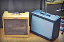
Hello there all, and welcome to another exciting episode of Mojotone’s Fix It Friday series. Last time on Fix It Friday, we replaced the power transformer in a Blues Junior with an upgraded Mojotone Blues Junior style power transformer. Today, we are going to continue modifying our Blues Juniors by moving the chassis and speaker into a new speaker enclosure. My speaker cabinet was just getting a bit road-worn and I was ready to spice it up, but the custom Mojotone Blues Junior replacement cab I’ll be moving into is actually slightly larger than the original, which allows for more cabinet resonance and what many users report to be a bigger sound overall.
In Image 1A below, you’ll see my new custom cabinet. I’ve chosen to go with the all new Blackout Tweed option offered by Mojotone which is super sleek but still has the texture of traditional tweed material. I’ve also chosen
and I’ve opted for a
(the small brown leather handle that originally came on my Blues Junior was hanging on by literal threads so I needed something beefier).

This list of tools and supplies needed for today’s project is short and sweet…
Nut Driver/Socket Wrench
For those who have been following along, you might recall that I left the back panel off of my old Blues Junior last time -- this is because I knew I would be switching cabinets soon and I would just have to take the back panel right back off again. But for those who are starting from the very beginning, we’ll quickly go over the process of removing your BJ chassis from its original cabinet.
First, we’ll need to remove all of the screws from the back panel and set them aside in a safe place. Next, we can take the chassis mounting screws out of the top panel of the cabinet. Finally, we can remove the chassis mounting screws from each side panel of the cabinet (there should be one on each side). Once this is done, you should have a group of screws that looks like those below in Image 2A.

Note : As you can see, there are three different sizes of screws in the bunch. Later on, when we are preparing to mount our chassis into the new cabinet, we’ll need to recall that the shortest screws should go into the bottom two holes on the back panel (if you choose to keep the tube cage mounted in the new cabinet), and the medium-length screws should occupy the remaining six holes in the back panel. The longest screws will actually not be used, as Mojotone’s cabinet does not require the chassis to be mounted this way.
To finish removing your BJ chassis from its original cabinet, you’ll need to disconnect the speaker cable from the chassis, disconnect the reverb cables from the reverb tank, and unscrews the white clamp which secures the reverb cables to the inside of the cabinet. Watch the video below for a demonstration…
Now it’s time to remove the speaker from the old BJ cabinet. To do this, you’ll use your Phillips head screwdriver or drill to remove the speaker’s mounting screws one at a time (Image 3A).

Note : Set your screws aside -- the Mojotone cabinet will use a different mounting method so we will no longer be needing these four speaker mounting screws.
In my case, I’ll be transferring this same speaker over to my new cabinet, but some people may want to take this opportunity to install a completely different speaker. In any case, we can set the speaker aside for now and turn our focus towards the reverb tank. We will need to unscrew the four mounting screws holding the reverb tank to the bottom of the cabinet, and then set the tank aside as well (Image 4A).

Note : Make sure you hold on to the reverb tank mounting screws as we will need these when installing the reverb tank in the new cabinet.
Now it’s time to prepare the new cabinet for the transfer, by removing its upper back panel and setting it aside. To do this, simply unscrew the back panel’s six mounting screws, and set the screws aside along with their decorative washers (Image 5A).
 Note : It is important to make sure these screws remain separate from the screws you removed from your old cabinet.
We can now move on to installing the speaker (either a new speaker or the one we removed from our old cabinet) into the new custom cabinet. Remove the nuts from the speaker mounting posts in the new cabinet (Image 6A) and then position the holes in the speaker over the mounting posts in the speaker baffle (Image 6B).

Once you’ve worked your speaker down the mounting posts and have it resting evenly against the speaker baffle, you can fasten down the nuts you removed a moment ago using your nut driver or socket wrench. Once your speaker is fastened down you should be looking something like Image 7A below.

Okay, we have our speakers in; next up is the reverb tank. The screws we removed from the reverb tank earlier should do a fine job of tapping into the bottom panel of the new cabinet. I’m going to screw mine in by hand without using pilot holes, however, if you are a pilot hole kind of person you are welcome to use a drill to make some pilot holes. For me, I’m going to lay my reverb tank in there where I want it and start screwing it down gently (Image 8A).

We’ve installed the speaker and reverb tank into our new cabinet. The only big thing left to do is mount the BJ chassis to the new back panel, and secure the back panel onto the new cabinet. Remember, with the Mojotone cabinet, the chassis/back panel is getting securely mounted into the mounting cleats inside the cabinet, thus we will not need to use the top panel and side panel mounting method which was used on our original Blues Junior.
First, let’s get our medium-length mounting screws (along with their accompanying washers) inserted through the six pre-drilled holes in the new back panel (Image 9A).

Next we can orient the chassis with the transformers down on our work surface, the electronics facing up towards us, and the tubes pointing towards us as well (Image 10A).

Now we can set our back panel on top of the chassis (with the threads of the screws facing down toward the chassis and the oval cutout closest to us), line up our six mounting screws with the six holes in the chassis, and start screwing them in a little at a time (Image 11A). It may take some playing around with to get everything seated just right, but it will happen and in the end it should be seated down like Image 11B below.

Okay, now comes the issue of the tube cage. This will all come down to personal preference, and my personal preference is to do away with the tube cage entirely. I don’t feel it is perfectly necessary to have in place, as I am comfortable with how well my tubes are protected without the tube cage. In real life, I’m going to just throw my tube cage out and be done with this, but for those of you who want to keep the tube cage, I’ll go through the process of how to properly get it mounted onto the new back panel.
Mojotone does not pre-drill for the tube cage because these are less of a ‘sure thing.’

Once we have our tube cages seated, we can tighten those three mounting screws back down to hold the tube cage in place while we drill holes for the other two screws. Grab a drill bit roughly the size of the screws and drill down through the two threaded inserts highlighted in Image 13A below.

After the holes are drilled, all we need to do is use the two shortest mounting screws (these were removed from the back panel of the old Blues Junior cab at the start of the project) to fasten down the tube cage.
Okay people, we’re on the homestretch now, I promise! It’s time to get the back panel and chassis mounted into the cab, so place the back panel, onto the cabinet’s cleats with the transformers facing down into the cabinet and the amp’s control panel facing up towards the top of the cabinet (Image 14A).

Before we fasten the back panel down, let’s make our lives easier by going ahead and connecting the speaker to the jack, connecting the reverb tank, and fastening the reverb tank wires down to the side of the cabinet (optional).
Finally, let’s grab the mounting screws and decorative washers that came with our new custom cabinet, and fasten everything down (Image 15A).

That’s it! It’s time to rock out in style. As always, thank you for stopping in to see what we’re up to. If you were able to follow along at home, we’d love to see pictures of your brand new custom Blues Junior so please send them in to
. Check out a side-by-side of my new and old Blues Junior cabs below. See you next time!

Meaning, the placement can vary a bit from amp to amp so it would be risky to pre-drill
. In order to mount the tube cage, we need to loosen the three mounting screws closest to the tubes, just enough to where we can slide the lip of the tube cage in between the chassis and the back panel. Refer to Image 12A below as a visual reference…