Free shipping over $99!
Fix It Friday: Voltage Test Points Every Amp Builder Should Know
Fix It Friday: Voltage Test Points Every Amp Builder Should Know
Published on
January 21st, 2021
Welcome back to Fix It Friday. This week, we are going to keep it very simple and straightforward by identifying some basic voltage test points in a very popular amp -- the 5E3 or Tweed Deluxe Style circuit. Again, this is a surface-level lesson but it should help you in a couple of ways...
The first way it can help has to do with new amp builds. Let's say you just finished assembling and soldering a circuit, either from a kit or from your own design. Before putting in all the tubes, turning it on, and letting it rip, you need to know if healthy voltage levels are reaching a few key points in the amp. Otherwise, you run the risk of doing some serious damage, potentially because of something small that could have been fixed quickly.
The next way it can help is in identifying issues in an older/used circuit. Components can wear out over time, as we all know, but sometimes it is hard to determine which component is causing all the fuss. Knowing a few basic test points can put you in the part of the circuit that needs addressing, and even more detailed testing can reveal the true "kink in the hose" so to speak.
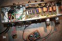
We only need one tool for certain today and that is an
. Image 1A, below, shows the multimeter I'll be using. You don't have to spend a ton of money on these, but if you're going to get one it's best to go ahead and purchase something that can test voltage in both AC and DC circuits. As long as we have a multimeter we can accomplish the main goal, but if your chassis is already in an existing cabinet you may also need a drill or
to get it out.
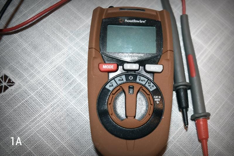
In my case, I'll be using an amp that has already been tubed and installed, so I'll need to remove it from its cabinet, and then remove the power tubes. Once this is done, lay the chassis on your workbench with the component board facing upwards, and the tubes/tube sockets pointing back at you (See Image 2A).
The first test point is going to be right at the filament wires on the pilot light. This voltage is always on with the amp and is not affected by a standby switch. We need to make sure we are getting right around 6.3 volts on the output and preamp tubes and 5V on the rectifier tube, otherwise we could have something open or short in our circuit, and this could actually cause serious damage to the power transformer. After done testing, turn the power off.
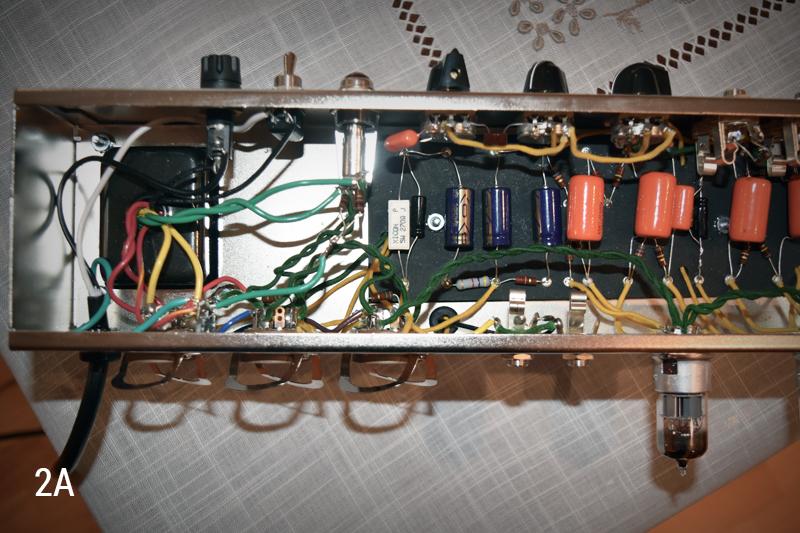
Alright, in order to properly perform this test, we need to make sure our rectifier tube is inserted, but none of our power tubes should be inserted. Also, we must turn our multimeter to Volts in AC (See Image 3A).

Now, turn on the power switch to your amp, let it warm up for about 15 seconds, and then flip the standby switch (if you have one). The amp should be fully on.
Your multimeter should have two leads coming off of it, one black one red; black is ground and red is hot. For ALL of the test points in this article, you will need to have your black lead making contact with a ground point (I always use a nice open space on my chassis). So, make the ground point connection with the black lead, and touch the hot lead to the point at which your filament windings are connected to the pilot light (See Image 4A).
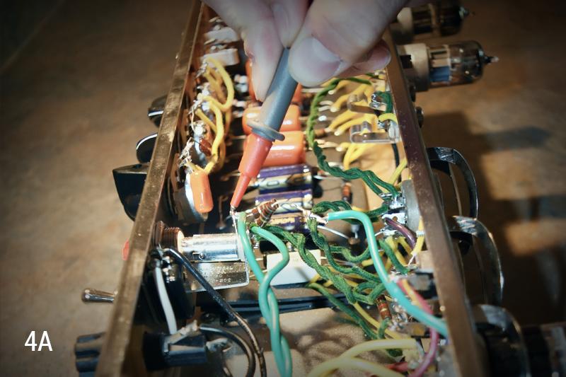
We should be seeing something along the lines of 6.3V here. If voltage is much higher or if it reads 0V, there could be an issue. If you are getting a good reading, we can move forward.
For the rest of these tests, we will need to have all of our power tubes installed (we will also need to have our amp connected to a speaker at this time). So, let's turn off the amp, insert our power tubes, connect a speaker, and then turn the amp back on.
The rest of these test points will all be measured in DC voltage so let's switch our multimeters over to DC before anything else. Once this is done, we are ready to go. I've attached a diagram that shows the remaining test points (all of which are eyelets on the component board) for my 5E3 Tweed Deluxe Style circuit (See Image 5A).

Depending on what amp you're working with and how familiar you are with said circuit, you may need to search for a voltage test diagram for that particular circuit. This is a diagram similar to the one above that should show various test points and the voltages you should be seeing at each.
Now you just dive on in and see what you get. You should be getting voltage readings within +/- 10% of the value specified on your diagram. If something is drastically off, you will know to start pinpointing the leads on certain components. This sort of hunting for the exact trouble maker can get tedious and misleading at times so if at any point you become unsure, please contact your local amp tech for better assistance.
My test points are looking pretty solid (and I happen to know this amp is in working condition), so I'm going to shut her down and reinstall the chassis in the cabinet so I can rock this thang! Hopefully this brief run down gave you some insight on basic test points and how they can help identify issues in a circuit. Please join us next time for another installment of Fix It Friday!

Please keep in mind Tube amps contain lethal voltages, please be careful and if there is any doubt, have a qualified tech do the work.
Note: This actually happened to me recently; I failed to clip some excess lead from the filament wires and the excess was making an accidental connection to another component. My transformer was getting way too hot and producing a smell. It was scary and silly and could have been prevented by performing this test!
Before installing tubes on a new fresh build: Test pins 3 and 4 of the output tube sockets (a standby switch would be closed at this point) for high voltage, reading on pin 4 should be a bit lower than on pin 3. Then, verify a negative voltage reading on pin 5 of both sockets. The reading should be -30V to -55V depending on the tube type. Taking this reading insures the output tubes will not immediately "red plate".
Take the same measurements again, and then take readings at all of the test points in the diagram.