Welcome back everyone. Today we’ll be picking up, once again, where we last left off with our NC3015 Amp Kit build. Last time, we finished the wiring portion of our build, which was incredibly exciting and rewarding! Now it’s time to clean up all of those solder joints and test out our amp.
Here’s a short list of tools you’ll need today:
- Wire Cutters
- Electronic Multimeter
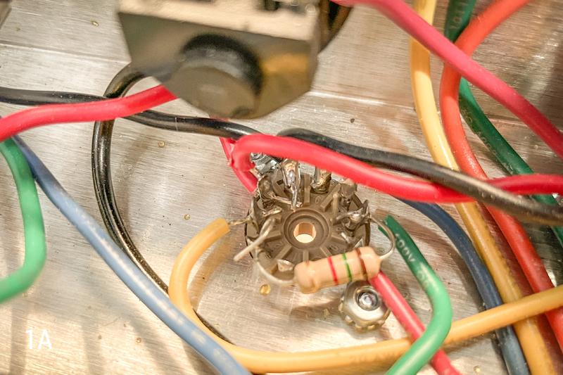
We want to begin by going back with our little wire cutters and trimming the excess lead material off of all of our solder joints (if you haven't already). This is extremely important, as often times if there is too much lead material coming out of a solder joint it can actually make contact with another joint and cause a short. This is especially important around tight areas like your tube sockets. Check Image 1A below for an example of how crowded those areas can get…
Once everything has been trimmed down (and you may well have done this while you were wiring, so you get bonus points), we’re ready to move on to the testing phase. We will conduct a series of tests that will increasingly engage the circuit and tell us just how close or far we are from being ready to fire this bad boy up for real.
To begin, make sure you insert your fuse into the fuse holder, and re-insert the loaded fuse holder back into its fixture on the chassis. Now, bust out your multimeter and turn it to the AC Volts setting. Next, insert the rectifier tube (EZ81) into its proper tube socket (this will be the tube socket closest to the power transformer). Then, turn the amp on (power switch only).
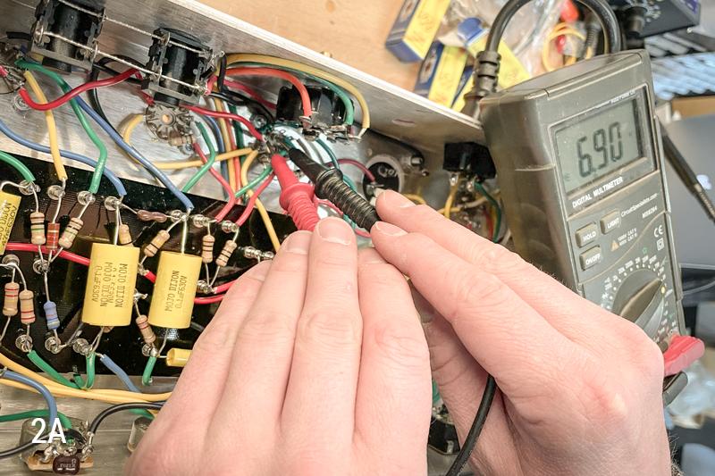
This first step is to test for filament voltage. This will tell us whether there are any shorts or opens in the filament. We’re going to be running this test on our first output tube, which is located directly under the impedance selector switch. Place one multimeter probe on pin 4, and one probe on pin 5; you’re looking for a reading of around 7 Volts. Take a look at Image 2A below…
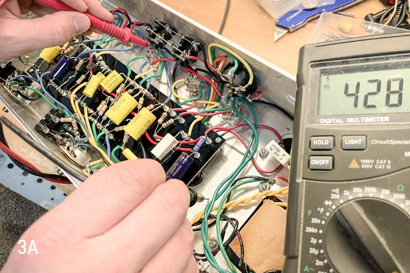
If you’re getting the proper reading at this point, you can flip the standby switch and change your multimeter to DC Volts. We now want to test for voltage on the plates of the tubes. This will need to be tested on pin 7 of your output tube sockets, and pins 1 and 6 of your preamp tube sockets. We are looking for high voltage here, so if you aren’t getting a higher DC voltage reading (somewhere around 400V), there could be an issue. Place the ground probe of your multimeter somewhere on the chassis surface, and place the positive probe on the above mentioned tube pins one at a time to check for voltage (Image 3A).
Once you’ve done this, you can test for high voltage on the screen of each output tube socket (pin 9). Again, ground probe on the chassis, and positive probe on the test point.
If you get good readings here, you now know that your power supply is operating and your tubes will turn on.
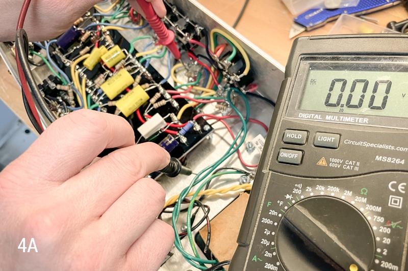
You can now test the voltage on the grid of each output tube, which will be on pin 2. Here, instead of high voltage, you want to see a reading of 0V. If you get a reading of more than 2V on your grids, you have an issue (Image 4A).
A proper reading here suggests that you will not have an issue with tubes red-plating. Once you’re good, you can power the amp down and let it sit for a few minutes. Next, you can install the rest of the tubes, and connect the amp to an 8ohm load that can handle 15W or more. Turn the amp on, let it warm, and then take the amp out of standby. Now you can re-test all of the previously tested DC Voltage points. When testing now, the voltage reading should be lower than you were seeing when the tubes were out and no load was connected (roughly a 100V difference).
Once these voltages are confirmed, we’re going to test both the output and preamp cathodes. The output cathode should read between 10V and 20V, while the preamp cathode should read around 2V with the exception of the one closest to the output section (it should be around 60V here). For the output section you’ll test pin 3 on each output tube socket (with your multimeter’s ground probe placed on the chassis). For the preamp section you’ll test pins 3 and 8 on each of the preamp tube sockets. Below is a breakdown of how each preamp tube socket should read...
Note: the "1st" preamp tube is farthest away from the output tubes, where the "3rd" is closest to the output tubes.
1st preamp tube socket = around 2V for pins 3 and 8
2nd preamp tube socket = around 2V for pin 3 and around 100V for pin 8
3rd preamp tube socket = around 60V for pins 3 and 8
If all of the above readings are correct, this tells us all of our tubes are working properly and operating at a safe level. You can now move on to audio testing...which we all know is the absolute best part.
Connect the amp to a speaker, if you haven’t already, and make sure the impedance of the amp and speaker match. Turn on the amp, let it warm, take it out of standby, and let her rip! Here’s a clip of what ours sounded like…
Now typically this is the part where I would walk through installing the chassis in its cabinet. However, we are currently waiting on a custom cabinet for this particular amp and once we have the cabinet, we will be sending the amp out to our good friend Hanan Rubinstein to be used in his studio at Daxxit Music in Fort Lee, NJ.
In previous articles we have covered the installation of chassis within amps, so I have every bit of confidence that if you've been following along this far, you'll be able to finish this up in no time!
Thanks again for tuning in and building with us. We hope to see you next time!